Dreaming about Drones
Development of nano-drones with custom PCB and autonomous navigation.
My Journey So Far
How It All Began
December 2023 – February 2024: The Seed of an Idea
I was in my third semester, buried under the pressure of an upcoming ODE exam. Unable to focus, I stumbled upon this YouTube video, and it changed everything. Watching the video sparked an idea—what if I tried building something like this? It stayed in the back of my mind, simmering as I navigated my growing interest in electronics.
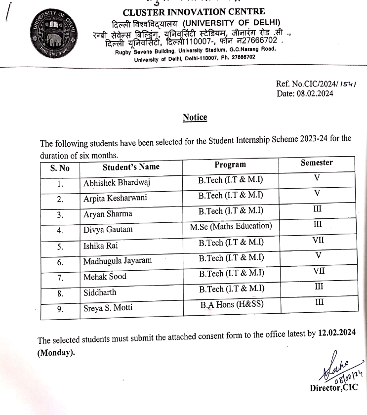
Those months were a whirlwind of experimentation. My exposure to LFR competitions, Arduinos, and Raspberry Pis deepened my fascination. Then came February, and with it, came a opportunity: my college launched a Student Internship Scheme (SIS), where students could pitch an idea to a professor and work on it collaboratively. Nervously, I pitched the nano-drone idea to a professor, and to my surprise, he agreed! To this day, I’m not sure why, but his immense faith in me has been a driving force ever since.
During this time, I also ordered a cheap Chinese drone to reverse-engineer it.My professor and I quickly realized this wasn’t feasible; ICs had scrubbed part numbers, and we couldn’t identify the components. This setback was one of the reasons we decided to build everything from scratch. Additionally, budget constraints played a significant role: Crazyflie drones cost around $250 each, while our entire project budget was $600 (which arrived late). These limitations meant our swarm concept had to adapt to fit within these constraints.
Coincidentally, I received the SIS selection email just after my exams—the perfect end to that chapter.
March – June 2024: Into the Deep End
Around the same time, I got selected for an internship at the Cyber-Physical System Lab, University of Delhi. By some twist of fate, this internship focused on micro-drones. My first month there was chaotic—I had no clue what I was doing. My first month there was pure chaos—I had no clue what I was doing. After diving into a mountain of literature, I felt completely lost. I still remember sitting in my professor’s office, groaning, “What are we going to do? This feels impossible.
Luckily, my professor was the chillest guy. That evening, I went home feeling defeated and crashed early. The next morning, I woke up to his text. He had found and sent me a manual on how to build a drone. After weeks of fruitless searching, this felt like a miracle. I was ecstatic. The following day, I thanked him in person, and he casually asked me to look at his whiteboard. There it was—the first circuit diagram of our prototype on his white board. He told me he’d spent the entire night studying it. To this day, I’m amazed by his dedication and ability to pull off such feats.
The next few months were brutal but rewarding. So, this was around April-May when I went to Lajpat Rai Market (for those unaware, this is the largest electronics market in Delhi, possibly in India)

It was my first time there, buying parts to get started. Little did I know this would soon become my regular pit stop—by now, I’d say I’m 60% proficient in navigating the shops there.
After gathering the components, I dived into the manual, building small projects: a voltage divider, gyroscope integration, calibration, and more. For the first few weeks, things went smoothly. However, when we reached the ESC (Electronic Speed Controller) stage, challenges arose. The manual relied on a pre-built ESC, which is a great option for most projects. But since we were working on micro-drones, we needed a smaller, custom alternative.
The ESC Struggles
My professor suggested using MOSFETs. Coming from a CS background, I had no idea what that meant. Vaguely recalling semiconductor physics from my JEE days, I turned to my all-time favorite teacher: YouTube. After watching countless videos, I felt confident enough to give it a try. I headed back to Lajpat Rai Market, bought a bunch of IRFZ44N MOSFETs (to this day, I’m unsure why I picked those—whether it was my professor’s recommendation or something I found online), and started testing the motors. And thus came my first greatest lesson:
“Always start small and build from there.”
I jumped straight into a full-fledged motor test, and… it didn’t work. Weeks of re-testing left me frustrated. My professor was busy, so the responsibility to figure it out fell on me.
Finally, after a call with my professor, I learned my second greatest lesson:
“Always read datasheets.”
It turned out the IRFZ44N MOSFET wasn’t suitable for operation under 5V because its gate voltage threshold was around 10V. This realization was a turning point. Most of my electronics knowledge has been acquired through this project—what seems obvious to an EE or ECE student was entirely new territory for me. It felt like landing in an unfamiliar city without a map
Taking a Step Back
Despite switching to different MOSFETs, success remained elusive. By July, I was at my wit’s end. I nearly gave up and stopped working for a month. During this time, I explored wireless communication and integrated components like the gyroscope and battery. Surprisingly, you don’t need more than five core components to get a basic drone running. —
A Spark of Hope
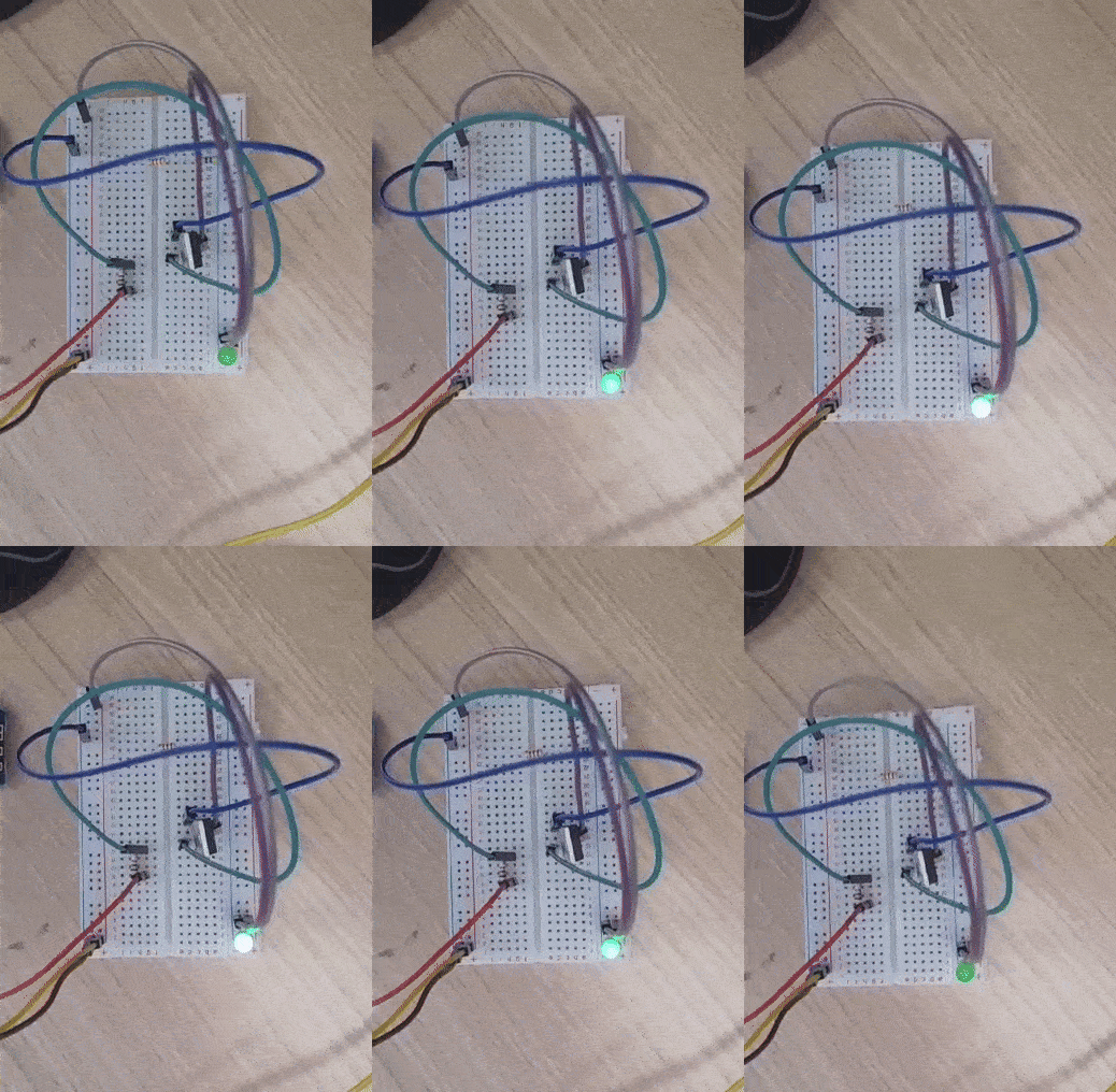
I explained the MOSFET issue to my professor. After a couple of days, he came up with two remarkable ideas. First, he suggested using the motor driver (TB6612FNG) that I had previously used for an LFR project. It wasn’t an ideal solution, but it was something—and for the first time in months, the motor moved! I can’t describe the joy of seeing it work after so many failed attempts. While this approach was a stopgap, it reignited my determination.
Next, we experimented with the Si2302DS MOSFET, which finally worked. Looking back, I realized I could have saved time by simply referring to the Crazyflie schematics, but this hands-on experience taught me so much. Working with SMD components and understanding circuit diagrams initially felt intimidating, like venturing into uncharted territory. Here,I learnt my third lesson,
“Just do it.”
This phase was a crash course in PCB design, which I had previously avoided due to its perceived complexity.
August 2024 – Till Now: The Acceleration Phase
By August, progress was slow, and my six-month internship was coming to an end. To say I was worried would be an understatement. I asked my professor what to do, and he suggested requesting a three-month extension alongside my final presentation. Thankfully, it was approved.
This three-month phase became the turning point. During this time, we developed three PCB prototypes: V0.1, V0.2, and V0.3. My professor was also teaching one of my elective subjects, which was project-based. I decided to continue this drone project as part of that course, giving it the hard deadline and structure it needed.
Iterating the PCB Designs
Once we confirmed motor functionality on the breadboard, we accelerated our efforts to design and refine PCBs. Each iteration marked a significant step forward, teaching us critical lessons:
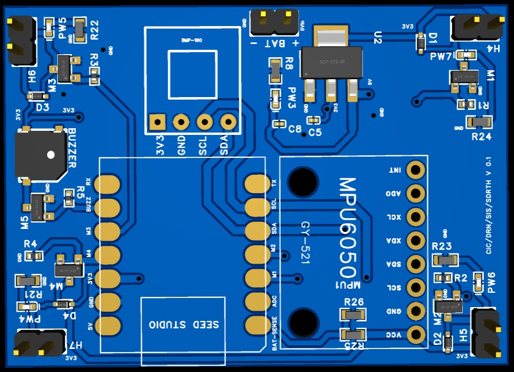
V0.1: The First PCB Attempt
Our first PCB design was an attempt to translate the breadboard setup into a more permanent form. While functional, it had several flaws:
- Size and bulk issues.
- Noise caused unreliable sensor readings.
- Debugging was time-consuming.
Despite its shortcomings, V0.1 validated the potential of moving to PCBs, and it became a foundation for improvement.
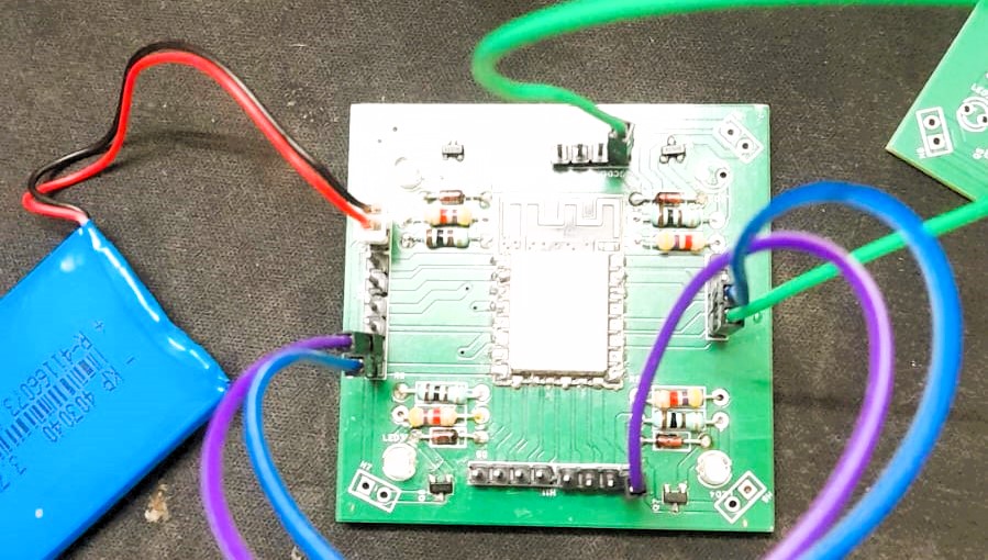
V0.2: Addressing Noise and Power Issues
Learning from V0.1, V0.2 focused on addressing noise and adding better power management. Key changes included:
- Optimized signal paths reduced interference.
- Added voltage regulator for power stabilization.
- USB-C debugging port for firmware updates.
V0.2 represented a cleaner, more efficient design that reduced the noise issues seen in V0.1. However, the size was still larger than desired, and further optimization was needed.
V0.3: A Compact and Robust Design
The final iteration, V0.3, was a culmination of everything we had learned so far. It featured:
- Integrated Motor Holders: This innovation ensured better mechanical stability and reduced vibration, a critical factor for drone performance.
- Refined Power Regulation: Further improvements to the voltage regulator ensured stable operation under varying loads
- Compact Layout: Components were tightly packed without compromising functionality, achieving the sleek design envisioned from the start.
V0.3 finally felt like a cohesive system, blending functionality, reliability, and efficiency.
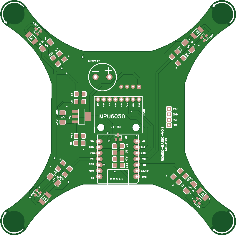
Each version not only brought us closer to our goal but also deepened my understanding of PCB design. It was a humbling yet rewarding process that showcased the importance of iteration and learning from mistakes.
A Stroke of Luck
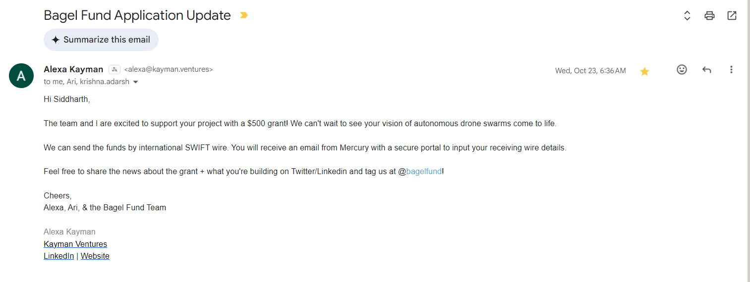
By November, my college officially ended the internship. Funds were running low, and deep-tech projects like drone development are expensive. Just when things seemed bleak, I stumbled upon The Bagel Fund. This incredible organization backs young innovators with micro-grants, and they generously supported the project with a $500 grant. Their contribution came at the perfect time and gave the project the push it needed.
Looking Ahead
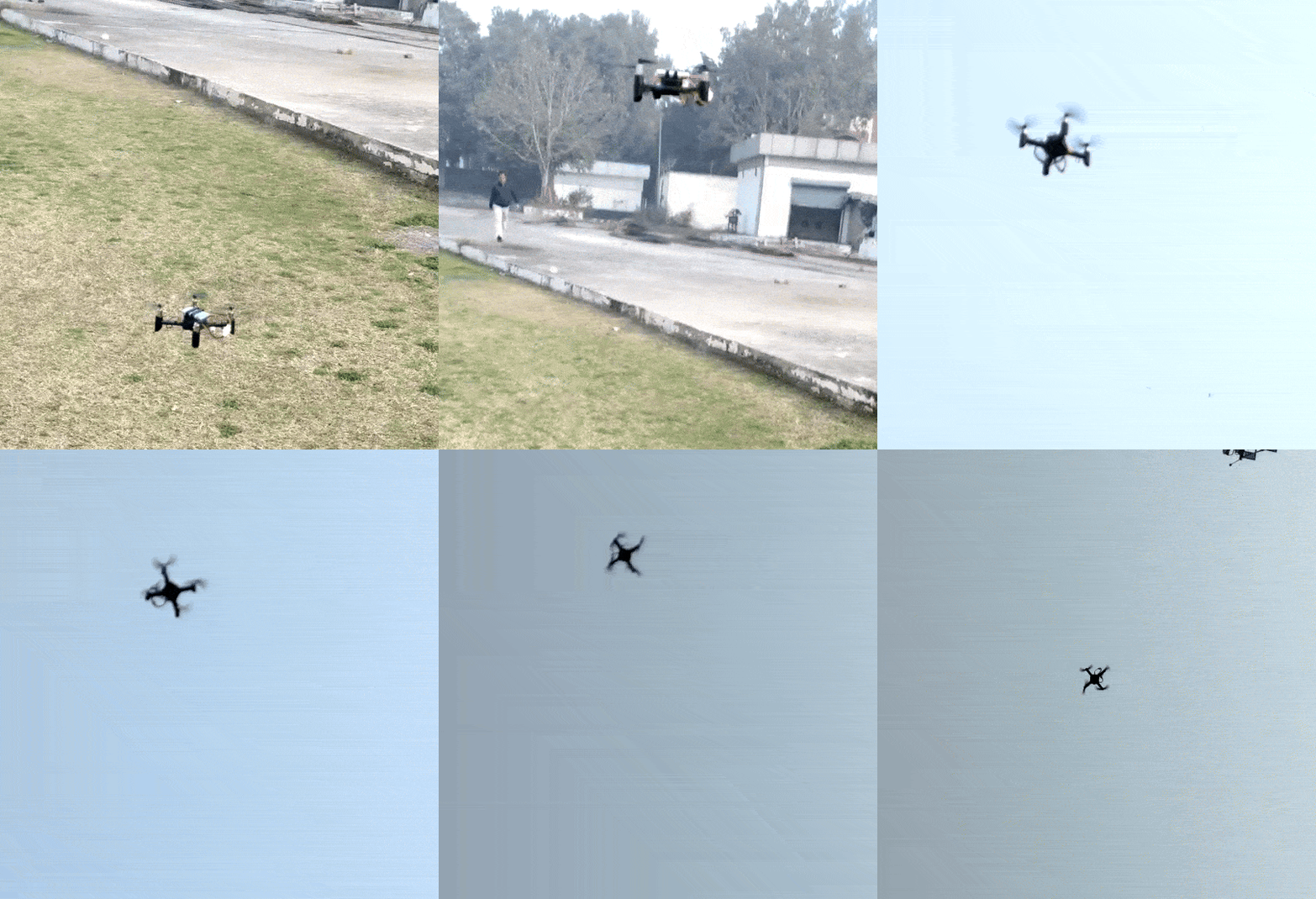
Here’s how the latest iteration looks:
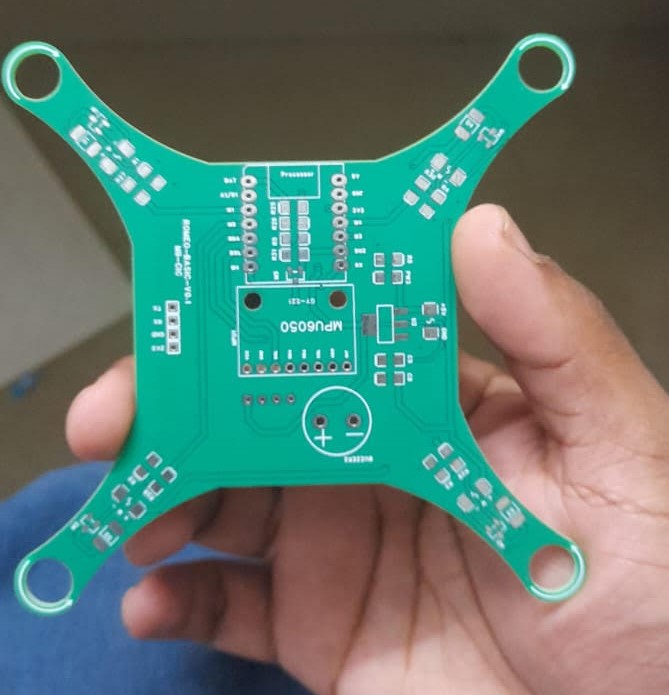
It’s not perfect, but it’s a significant milestone, and I’m proud of how far it has come. There’s still a long way to go, and the journey is far from over. I plan to document future iterations in separate blog posts, sharing each step as it unfolds.
Thanks for reading share your thoughts @sid_899 or email me.